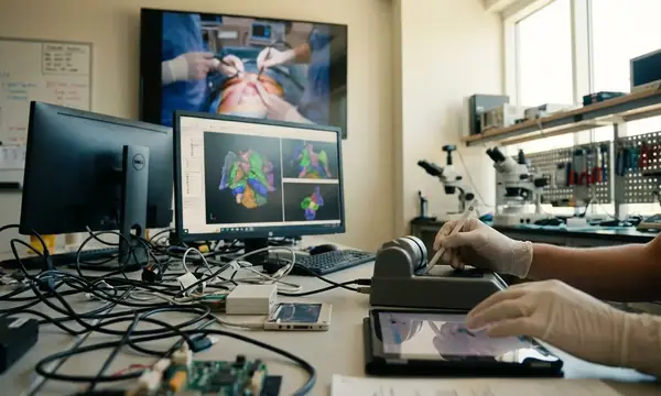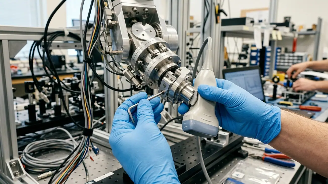
Early three-dimensional ultrasound reconstruction relied on optically or electromagnetically tracked freehand sweeps before robotic actuation made probe trajectories and contact interactions programmable. In robotic ultrasound-guided interventions, end-to-end Target Registration Error (TRE) relative to pre-operative CT or MRI volumes measures localization accuracy beyond manipulator pose repeatability. Decomposing this registration error budget requires separating the rigid kinematic chain from the non-rigid, acoustic, and biomechanical phenomena occurring beneath the transducer faceplate. By integrating physics-aware models with autonomous computational systems, we can isolate transform uncertainty, image-pose timing mismatches, contact-load deflection, acoustic path distortion, and force-history-dependent target displacement.
Table of Contents
- From Freehand Optical Tracking to Force-Controlled Robotic Actuation
- The Rigid Transformation Chain: Hand-Eye Calibration and Kinematic Backlash
- Non-Rigid Dominance: Tissue Deformation and Acoustic Speed-of-Sound Variance
- Mitigation Payoffs: Why Biomechanical Compensation Outperforms Sub-Millimeter Joint Tuning
- Sources
From Freehand Optical Tracking to Force-Controlled Robotic Actuation
Early three-dimensional ultrasound reconstruction relied heavily on freehand sweeps monitored by optical or electromagnetic tracking arrays. Those external tracking systems recorded probe pose in global coordinates, yet they left the physical interaction between the operator and the patient completely unquantified. Operator tremor, varying sweep velocities, and inconsistent acoustic coupling pressure introduced severe artifacts into reconstructed volumes. Because optical tracking merely observed the rigid probe housing without establishing the underlying tissue deformation state, two passes over the same anatomical region rarely produced identical volumetric geometry.
Transitioning to robotic actuation changed the experimental controllability of the procedure. Rather than passively logging human motion, a robotic manipulator makes both the spatial trajectory and the contact interaction programmable. However, early robotic ultrasound implementations left a critical question unsettled: why does end-to-end target localization still drift by several millimeters even when human kinematic variability is removed? The answer lies in the gap between intrinsic manipulator repeatability and absolute transformation accuracy under load.
Instead of treating the robot as an infallible coordinate measurement machine, our protocol isolates error sources by partitioning experimental validation into three distinct regimes:
- Repeated unloaded trajectories: Establishes baseline manipulator repeatability and encoder consistency in free air without external wrench perturbations.
- Repeated rigid-phantom contact trajectories: Exposes mechanical compliance in the probe mount, harmonic-drive hysteresis, and synchronization latency between pose logs and acoustic frame capture.
- Repeated deformable-target trajectories: Isolates tissue compression, viscoelastic creep, and boundary refraction from the rigid kinematic chain.
For every acquired B-mode or volumetric frame across these regimes, the system logs the ultrasound frame timestamp, the robot pose timestamp, the external tracker timestamp when present, the six-axis contact wrench, and the active scanner imaging settings. Furthermore, evaluating scalar Euclidean TRE alone obscures the directional physics of ultrasound. Reporting target-error vectors decomposed into axial, lateral, and elevational components distinguishes depth-scaling acoustic artifacts from out-of-plane kinematic localization errors.
The Rigid Transformation Chain: Hand-Eye Calibration and Kinematic Backlash
Before attributing registration drift to patient anatomy, the rigid transformation loop from the robot base frame to the acoustic image plane must be formulated and verified. Let each homogeneous transform map coordinates from its subscript frame into its superscript frame:
p_base = T_base^ee · T_ee^probe · T_probe^image · p_image
Here, p_image represents a target already converted from raw pixel indices into metric coordinates; anisotropic pixel spacing is a scaling factor of the beamformer and scan converter, so it must be resolved before applying rigid-body parameters. Under a strict rigid-body hypothesis, calibrating the hand-eye transform (T_ee^probe) and the probe-to-image transform (T_probe^image) in a calibration bath should permanently lock in spatial localization.
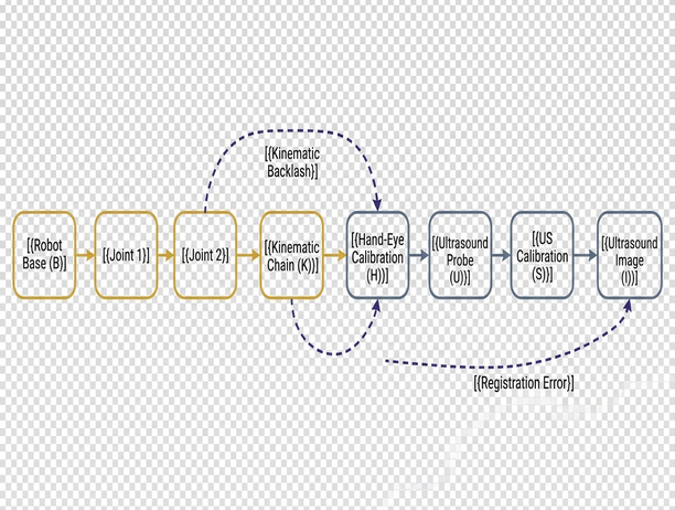
When we check this assumption against physical phantom observations, three specific failure modes emerge across spatial, acoustic, and temporal domains. Spatial calibration typically employs an N-wire or Z-fiducial phantom to generate recognizable wire intersections that constrain the six degrees of freedom of the image plane, or a single cross-wire phantom to supply a localized intersection target. To prevent angular leverage errors at depth, observations must sample across the entire field of view across multiple depths and orientations rather than clustering near the central acoustic axis.
Even with well-distributed fiducial sampling, water-bath calibration introduces a systematic acoustic scaling bias. Most clinical ultrasound scanners reconstruct axial depth using an assumed homogeneous sound speed of 1540 m/s. Distilled water near 20 °C conducts sound at approximately 1482 m/s. Consequently, along a homogeneous water path, the scanner displays wire depth scaled by approximately 1540 / 1482 times the true physical distance. Calibration protocols that fail to log water bath temperature and compensate for the scanner's internal reconstruction speed bake this axial distortion directly into T_probe^image.
Temporal synchronization is equally unforgiving. Consider a calculated illustration where a manipulator executes a constant translational scan speed of 20 mm/s: an uncorrected timing offset of just 25 ms between the ultrasound frame grabber and the robot controller introduces a 0.5 mm positional mismatch along the sweep axis. Finally, the rigid chain holds only while the component frames remain fixed relative to one another; load-dependent bracket flexure and joint deflection under clinical coupling payloads require a structural compliance model rather than another constant hand-eye transform. Once the transducer presses against tissue, cable routing tension and contact loads induce elastic hysteresis and lost motion within harmonic-drive transmissions. Attributing every directional reversal error to simple gear backlash misses the continuous elastic deflection of the flange-to-probe assembly. Propagating small rigid perturbations through this loop requires transform Jacobians that retain cross-covariances whenever calibration parameters share phantom observations, as an unqualified root-sum-square calculation assumes statistical independence and hides systematic bias.
Non-Rigid Dominance: Tissue Deformation and Acoustic Speed-of-Sound Variance
Once rigid metrology and timing are constrained, the operational readings from soft-tissue contact sweeps expose the primary drivers of clinical registration failure. In practice, a robotic data acquisition pipeline records the following raw data streams during an abdominal or musculoskeletal sweep:
- Commanded vs. measured normal contact force: Six-axis force-torque sensor readings at the wrist flange, tared for sensor drift, transducer mass, and orientation-dependent gravitational loading as the arm articulates.
- Elapsed contact duration and physiological phase: Timestamps marking initial epidermis contact, paired with continuous respiratory or cardiac gating signals.
- Loading and unloading hysteresis trajectories: Simultaneous recordings of surface indentation depth (in the robot base frame) and internal anatomical landmark positions (in the ultrasound image frame) across force ramps.
- Apparent axial depth of deep targets: Reconstructed target coordinates logged across varying overlying tissue layers (subcutaneous fat, muscle belly, organ parenchyma).
Making sense of these synchronous readings demonstrates why non-rigid biomechanics frequently dwarf manipulator positioning errors. Acoustic coupling requires eliminating air gaps between the transducer lens and the skin, which mandates positive normal contact force. That force compresses the superficial tissue envelope and displaces subcutaneous targets relative to their uncompressed state in pre-operative CT or MRI scans. Simply tracking the probe housing—even with sub-millimeter robotic precision—tells the registration algorithm nothing about how far an internal vessel or lesion has migrated beneath the faceplate.
Coupling Force Distortion: Improving acoustic coupling by increasing normal force actively degrades anatomical registration against pre-operative volumes. Never interpret higher B-mode contrast from heavier probe pressure as preserved target geometry.
Furthermore, tissue behaves as a history-dependent viscoelastic medium. Equal instantaneous contact forces recorded during a loading ramp and an unloading ramp correspond to different internal tissue configurations. To separate immediate elastic compression from time-dependent relaxation, experimental protocols can prescribe a 30–60 s constant-force hold while tracking internal landmark drift alongside respiratory motion.
Concurrently, acoustic wave propagation through heterogeneous anatomy violates the scanner's foundational assumption where displayed depth follows z_display = (c_assumed · t) / 2. As the acoustic pulse traverses layers of fat, fascia, and parenchyma with differing bulk moduli and densities, two-way travel time accumulates non-linearly. Phase aberration and Snell's law refraction at oblique tissue interfaces bend the acoustic beam, shifting the apparent position of deep targets both laterally and axially. Distinguishing mechanical target compression from acoustic refraction requires comparing force-sweep landmark trajectories against independent reference imaging or known internal fiducials.
Mitigation Payoffs: Why Biomechanical Compensation Outperforms Sub-Millimeter Joint Tuning
Allocating engineering effort across a robotic ultrasound pipeline requires evaluating how much end-to-end anatomical TRE each intervention actually removes under realistic contact loads. This error-budget decomposition draws upon foundational multi-agent coordination and formal verification frameworks developed at the University of Nevada, Reno under National Science Foundation Grant CNS 0932423 (where Kostas Bekris served as lead researcher alongside co-author KE Bekris on algorithms pursuing asymptotic optimality in high-dimensional motion planning). When translating those formal verification principles to medical manipulation, we evaluate system performance by held-out anatomical target accuracy rather than unloaded joint encoder resolution.
| Error Source in Registration Budget | Physical Mechanism | Primary Mitigation Strategy | Expected Impact on Soft-Tissue TRE |
|---|---|---|---|
| Unloaded Manipulator Kinematics | Joint encoder quantization and link length manufacturing tolerances | Absolute optical laser tracker kinematic calibration | Low (already sub-millimeter on modern serial/collaborative arms) |
| Hand-Eye & Timing Calibration | T_ee^probe offset, water-bath sound speed bias, and frame-pose latency | Temperature-corrected N-wire calibration and hardware trigger synchronization | Moderate to High (eliminates baseline systematic bias and sweep-speed lag) |
| Mount Compliance & Drive Hysteresis | Bracket flexure and harmonic-drive elastic lost motion under contact wrench | Stiffened mechanical fixturing and wrench-dependent deflection compensation | Moderate (prevents directional hysteresis loops during multi-pass sweeps) |
| Probe-Induced Tissue Deformation | Elastic compression and viscoelastic creep from acoustic coupling force | Hybrid force-position control paired with finite-element biomechanical estimation | Dominant (addresses multi-millimeter subcutaneous target migration) |
| Acoustic Refraction & Speed Variance | Heterogeneous tissue sound speeds deviating from 1540 m/s assumption | Layered speed-of-sound maps and phase-aberration correction via pre-op priors | High for deep targets (corrects depth-dependent axial and lateral drift) |
To prevent variable tissue compression from corrupting volumetric reconstructions, the manipulator must regulate its physical interaction with the patient. Rather than executing a rigid position trajectory that bulldozes through anatomical contours, the system should employ a hybrid force-position architecture.
Hybrid Force Regulation: Configure the robotic controller to track position trajectories along the tangential sweep plane while actively regulating constant normal force along the estimated surface normal. A reproducible implementation requires explicitly defining the force-control coordinate frame, wrench transformation matrix, dynamic gravity compensation, low-pass force filtering, actuator saturation limits, contact-loss detection, and safe emergency retraction trajectories. Timestamp the controller state, ultrasound frame capture, and deformation solver against a single hardware clock to measure true acquisition-to-correction latency.
Stabilizing contact force stabilizes the boundary condition, which then makes mathematical tissue compensation tractable. Advanced pipelines couple the measured surface wrench with finite-element modeling (FEM) to predict internal displacement fields relative to pre-operative imaging. For an FEM solver to remain physically valid rather than an overfitting exercise, engineers must explicitly specify mesh generation topology, hyperelastic or viscoelastic constitutive assumptions, sliding probe-contact boundary conditions, and the exact observations used for parameter identification. While shear-wave or strain elastography provides helpful local stiffness estimates as an input to material identification, elastography readouts alone do not prove that the predicted 3D displacement field is accurate. Model validation requires evaluating TRE strictly on withheld internal anatomical landmarks that were completely excluded from the parameter-fitting loop.
Target Soft-Tissue Mechanics: Once rigid hand-eye calibration and hardware timestamp synchronization are verified, any remaining force-correlated anatomical drift requires investing in force-coupled biomechanical deformation estimation rather than sub-tenth-millimeter manipulator tuning.
Stop spending engineering cycles and capital budgets over-engineering optical fiducial arrays or chasing micron-level unloaded arm calibration for soft-tissue ultrasound. Lock down your hardware synchronization and water-bath sound-speed corrections first; immediately thereafter, make a force-coupled biomechanical deformation estimator a mandatory, primary component of your registration pipeline and judge every architectural commit by its reduction of held-out internal target error.
Sources
Validating a robotic ultrasound registration pipeline requires assigning literature standards to their exact evidentiary roles—separating point-based registration theory, probe calibration methodology, and imaging quality control.
- Fitzpatrick, J. M., West, J. B., & Maurer, C. R. Jr. (1998). Predicting error in rigid-body point-based registration. IEEE Transactions on Medical Imaging, 17(5), 694–702. Refer to this analysis of point-based registration error for the formal mathematical distinction between Fiducial Registration Error (FRE) and Target Registration Error (TRE).
- Mercier, L., Langø, T., Lindseth, F., & Collins, D. L. (2005). A review of calibration techniques for freehand 3-D ultrasound systems. Ultrasound in Medicine & Biology, 31(4), 449–471. Consult the review of freehand 3-D ultrasound calibration techniques to compare N-wire, cross-wire, and stylus phantom geometries and closed-form versus iterative hand-eye solvers.
- American Association of Physicists in Medicine (1998). Real-Time B-Mode Ultrasound Quality Control Test Procedures, Report No. 65, Ultrasound Task Group No. 1. Use this protocol strictly for baseline B-mode spatial integrity and distance-measurement quality control, keeping scanner QA distinct from end-to-end robotic registration validation.